
Microchip Failure Analysis
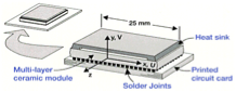
Figure 1. Typical chip soldered to circuit board.
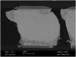
Figure 2. Solder joint deformation and cracking. |
Electronic gadgets are a familiar part of our everyday lives, but perhaps less familiar are the design challenges that are faced by manufacturers of these devices. In this article we will look at the common material property of thermal expansion, and specifically what happens when two materials that expand and contract at different rates are fastened together as part of an assembly and then heated and cooled.
Figure 1 shows a typical chip soldered to a printed circuit board. Normal operation of chips produces significant quantities of heat and as the chip is cycled on and off with normal device usage, the chip and printed circuit board temperature rises and falls. In this case the chip package material is a ceramic, and it is attached to printed circuit board made of fiberglass reinforced plastic.
While it is known in general that circuit boards expand and contract at an amount of about 3 times more than ceramic chip packages, what was not known in this particular case was that this difference was actually closer to a factor of four. This was not discovered until device failures were reported and investigation revealed deformation and cracking of the individual solder joints as seen in Figure 2.
This cracking is caused by fatigue; each time the device is turned on and off; the printed circuit board stretches relative to the ceramic, deforming and eventually cracking the solder joints. Strain gage testing was conducted, and the materials were found to be too dissimilar for this application.